BSI Couplings - 156 Super-Sprinter
156 » Under the floor » Drive Line • Couplings • Under frame photos
BSI Couplings - 156 Super-Sprinter |
|
156 » Under the floor » Drive Line • Couplings • Under frame photos | |
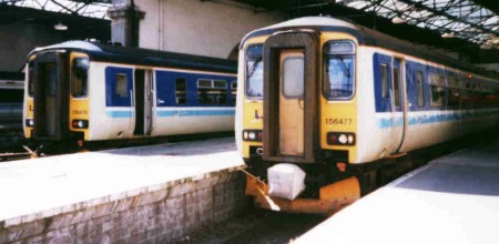
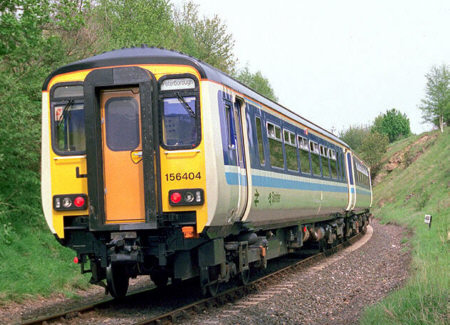
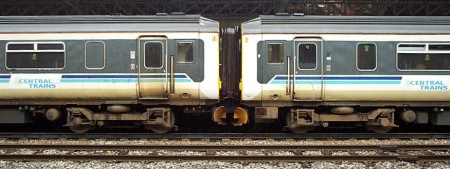 | 156422 coupled to 156418 at Nottingham on 20.July.2002. |
The use of automatic couplings allows units to join to form longer trains, or to detach portions, without the need for shunting staff on the track. It is therefore quicker and safer.
Since the mid 1970s British Rail had been using 'Tightlock' automatic couplings on EMUs, and these had also been used on some of the Railbus units built in the early 1980s.
A smaller low-weight design, the 'Compact' produced by Bergische Stahl Industrie (BSI), had first appeared in the UK on the Metro-Cammell built trains for Tyne & Wear Metro in 1978.
When BR's Provincial Sector drew up a specification for it's replacement DMU fleet, it standardised on the BSI Compact coupling, with a CK2 type head.
Prototype Sprinters 150.001/2 and 151.001/2 were the first to feature BSI couplers (although as built, they had an additional brake pipe connection on the coupler head and were incompatible with later build units).
The post-privatisation class 170s 'Turobstars' feature Compact couplings to allow compatiblity with the 15X Sprinter fleet, although the class 156s required a minor wiring alteration before they could work with 170s.
Other recent builds of UK Multiple Unit have used 'latch-type' couplings from Scharfenberg and Dellner.
The Compact is a centre buffer coupling which takes all traction and buffing loads, therefore side buffers are not provided.
The coupling heads are integral with the drawbar. The design is such that there is no freedom of movement between couplers when connected, and all relative movements between vehicles are accommodate at the drawbar pivot.
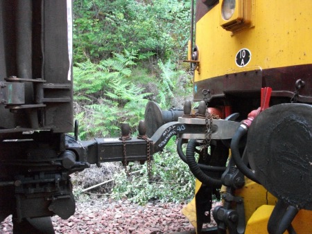
In the event of a unit failure, assistance by locomotive is possible with an emergency adapter coupling (which is carried on board some units).
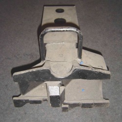
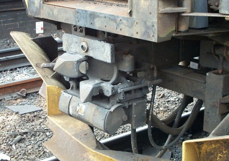 | The Compact coupling comprises of 3 parts: Pneumatic, Mechanical and Electrical.
|
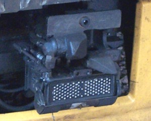 | The Electrical Connection Box has a cover to protect it from dirt. When opposing couplers engage, the cover rolls open to allow the electrical contacts to connect. There are 50 fixed pins on the right side, and 50 moving pins on the left side, plus 3 more in the centre. Sprinters use only 42 'train wires', so 11 pins are spare. |
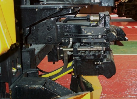 | On the left hand side is the Uncoupling Mechanism. When the Uncouple button is pressed in the cab, an air-powered piston pushes the uncoupling lever outwards, causing the coupling pin to be retracted. The forward spike on the uncoupling lever should be held in position by the Latch-Pin on the opposing coupler until the units have separated. If units with incompatible or defective couplings need to be coupled to clear the line, the electrical connection boxes can be retracted using the 'tommy bars' provided on each side of the coupling. |
 |
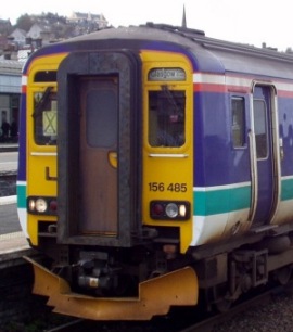
Cab-End CouplingsIn addition to the automatic coupling, the cab ends of units also have:
Photo: Steve Jones |
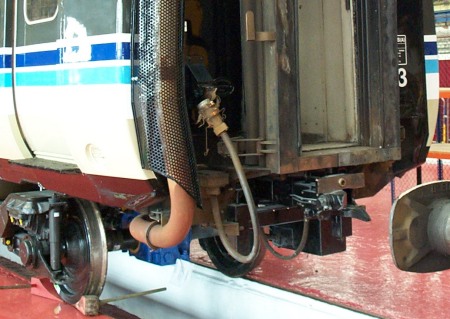 |
Inner-End CouplingsThe couplings at the intermediate ends of units are semi-automatic. They have only mechanical and pneumatic couplings, therefore a separate 42-way electrical jumper cable is provided. Uncoupling is done manually using the uncoupling lever. |
Class 156s are gangwayed at both intermediate and cab ends. The gangway opening is 550mm wide.
Each gangway is suspended by 6 'flexitors'. There are 2 large flexitors either side of the gangway at floor-height, 2 smaller ones which are attached to the drawbar and move the gangway when the coupler moves, plus 2 more inside the top of the rubber gangway shroud.
The faceplate of the gangway has anti-friction pads affixed to the right hand side and a lamp bracket is provided on the left hand side.
Coupling and Uncoupling
The coupling and uncoupling of units is fully automatic, under the control of push buttons in the driving cabs.
Procedure for attaching units:
Procedure for detaching units: